school
Formula Sae 2022-2023 Season
For my first season on FSAE, I was tasked with the development of a side diffuser.This project concluded successfully, and contains all aspect of a full engineering lifecycle including research, concepting, development, manufacturing, testing, and cost reporting.
context
During this season, our team was transitioning from tubeframe chassis towards a carbon monocoque chassis. Because of this, we had to redesign our side diffusers to fit the new chassis.The goal for me was to design a new side diffuser which had the following criteria:
1. Perform as well or better than the previous design.
2. Improve the mounting system, reducing the time from 15 minutes to under 2 minutes
Literature Review

Concepting
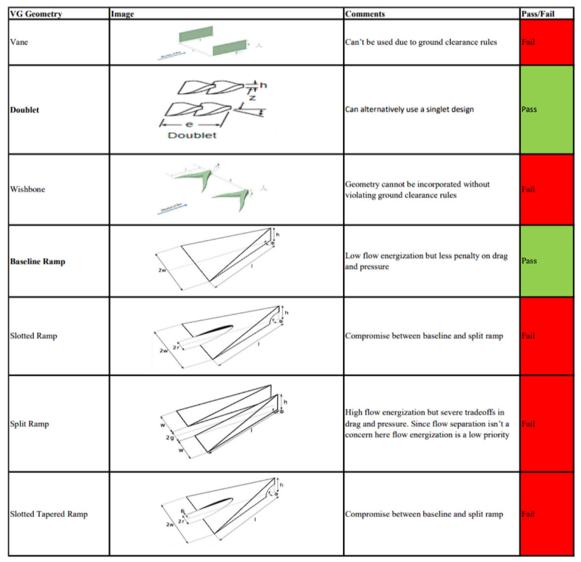
When we could, it was important to explain why we chose certain designs, since the competition judges really emphasized that part of the process.Below are the pass/fail selections for the vortex generator geometry, as well as different iterations of the side diffuser.In the end, our design choices were limited by our manufacturing capabilities, so we had to simplify things.

Manufacturing
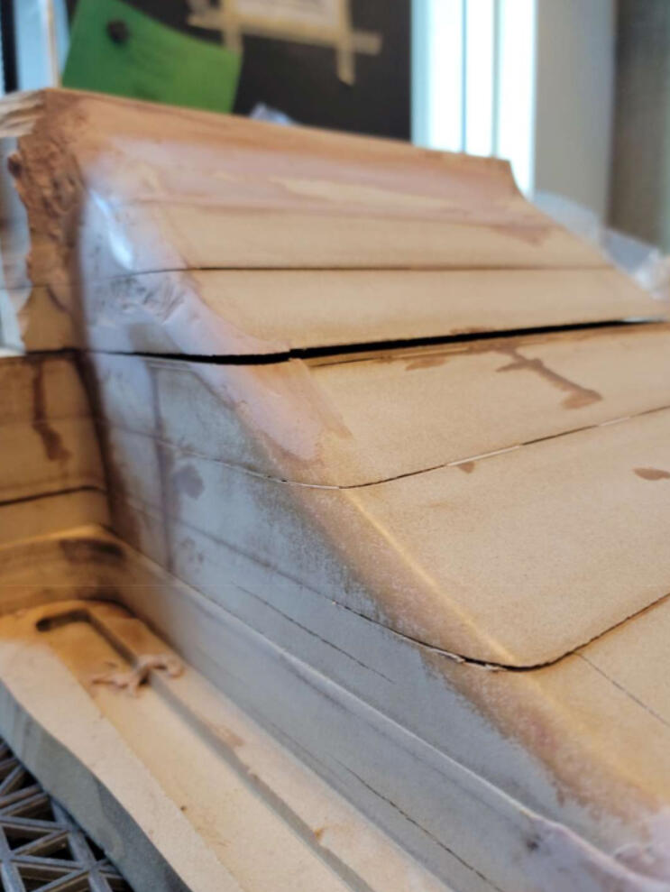
The manufacturing phase definitely brought the biggest challenges in this project. We pulled quite a few late nights to get everything done in time for the competition!The toughest part was that in order to make the diffuser out of CFRP, we needed to create the largest CNC mould ever in UBC FSAE’s history. We even had to take apart the CNC table just to fit the geometry!Below is a collection of images I took during the manufacturing process.

Since we were just making a mould, we realized later on that we could substitute the MDF for Polystyrene
When the mould was complete, we put it in the autoclave to outgas chemicals from the MDF, which led to the blocks separating, requiring additional post processing.

Toolpathing
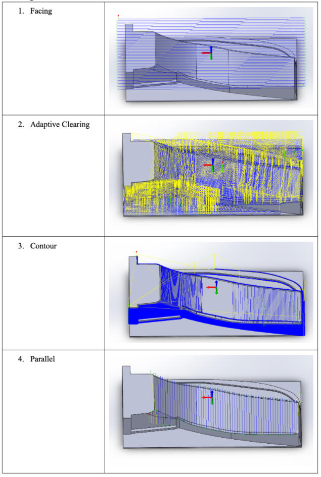
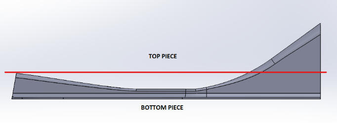
Included below are some images which demonstrate the toolpath, and the thought process behind the mould assembly.Since the mould was so large, we decided to split the mould into two parts so they could be CNC'ed individually, then reconstructed afterwards for the final mould


Mounting
As mentioned earlier, one of our project goals was to cut down on mounting time. So, we invested quite a bit of time finding a spot on the chassis that was easy to access.Since the CFD results only apply to the location specified in CAD, it was crucial to accurately mount the side diffuser in the same place to ensure real-life performance matched the design. We spent a lot of time creating a jig based on the chassis jigging table to help us find the exact installation point for the mounting devices.
conclusion
Overall, the project was a success. The initial goals set out were accomplished.However, there are a few improvements that could be made for next time. The most important thing in projects like these is to learn, and reiterate better next time.The biggest takeaway are the improvements we could make in the manufacturing process.1. Mentioned earlier, the outgassing of MDF resulted in the blocks separating. In the future, this step should be done before gluing the pieces together
2. Instead of machining the edge/boundary of the mould, we could instead have just attached a block towards the edges afterwards, saving lots of post-processing time


